
I’m currently rewiring a part of the Monsputer’s CPU board that was implemented with several patches. I’m reusing an Atmel CPLD used for another board. A problem with this chip: it’s a TQFP package. Without a PCB, it’s difficult to connect to the pins … or maybe not.

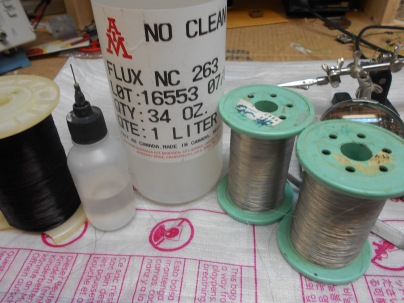
With common tools and a steady hand, it’s possible to connect very fine magnet wires to the pins. A soldering iron with a needle tip, some tweezers, a magnifier (or a stereomicroscope), some liquid flux, an x-acto knife. Some spools of enameled wire (#36 for signals, #26,#24,#22 for power), some tinned wire (#32,#36) for direct connections. The flux is an essential ingredient to a good solder.
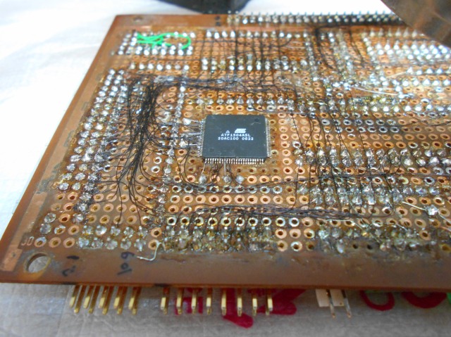
Here is the culprit, with many connections made already:


To connect to the pins, the insulation on the wire must be removed. For convenience, we allow two ends when finishing a net and beginning another: about 5 mm of nude copper. When the current net is completed, an half is used for the end of the current wire, and the other half is used for starting another net. In middle net points, we remove 3 mm of insulation. For the TQFP package, we make all nets ending on the TQFP. Instead of 2.5 to 3 mm, we only need about an half of a mm.
To cut the insulation, we do 8 cuts to scratch the enamel. While there are enamels that melt for soldering, this may cause problems. The 8 cuts are done with a hand held x-acto or similar knife. Here, the x-acto is shown in 2 positions. Before soldering to the TQFP, the exposed copper wire should be tinned. With a bit of flux, a steady hand (“doigts de fée”), place the wire end on the TQFP pad, heat the pin and the connection is done!
